
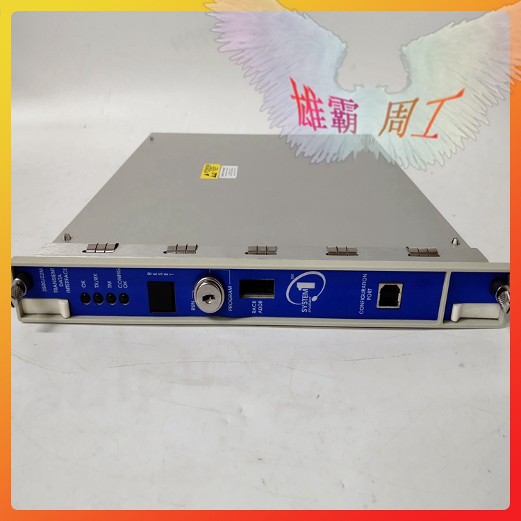
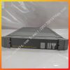
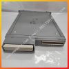

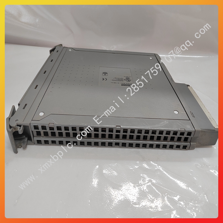
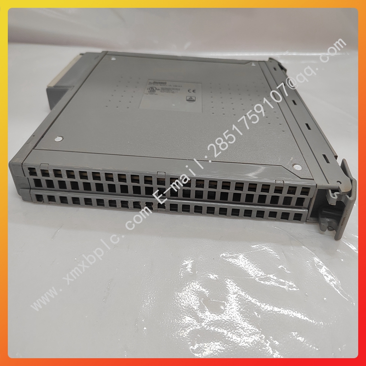
T8300 TMR Expander Processor Module ICS TRIPLEX
T8300 TMR Expander Processor Module ICS TRIPLEX


| Brand Name | ICS Triplex |
| Model | T8300 |
| Product type | N/M |
| Condition | New |
| Gross Weight | 1kg |
| Packing Size | 12.6″ x 7.9″ x 8.8″ (30 cm x 20 cm x 20 cm) |
| Country of Origin | USA |
| Lead Time | In Stock |
| Shipping Port | Xiamen |
| Payment | T/T |
| Sales Price | Inquiry |
| Color | Depends on material |
| Warranty | 12 months |
| Lead time | 3-7 work days |
| Courier partners | FedEx,DHL, UPS, TNTand EMS |
PD-T8300 Trusted
Rockwell Automation Publication PD-T8300 Issue 15
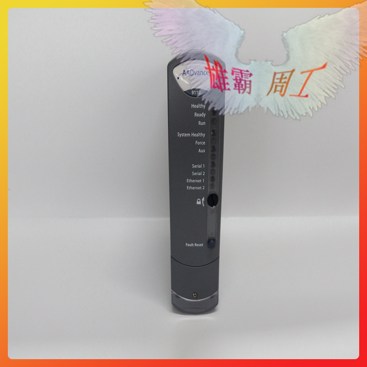
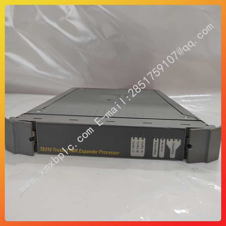
Trusted TMR Expander Processor
Product Overview
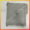
The Trusted® TMR Expander Processor Module resides in the processor slots of the Trusted
Expander Chassis and provides the ‘slave’ interface between the Expander Bus and the Expander
Chassis Backplane. The Expander Bus allows multiple chassis systems to be implemented using
Unshielded Twisted Pair (UTP) cable connections whilst maintaining the fault tolerant, high
bandwidth Inter-Module Bus (IMB) capabilities.
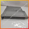
The Module provides fault containment for the Expander Bus, the Module itself and the Expander
Chassis, ensuring that the effects of these potential faults are localised and system availability
maximised. The Module is fault tolerant with HIFT TMR architecture. Comprehensive diagnostics,
monitoring and testing provide rapid fault identification. Hot-standby and module spare
configurations are supported, allowing automatic and manual repair strategies
T8300 Features:
• Triple Modular Redundant (TMR), fault tolerant (3-2-0) operation.
• Hardware Implemented Fault Tolerant (HIFT) architecture.
• Dedicated hardware and software test regimes which provide very fast fault recognition and
response times.
• Automatic fault handling without nuisance alarming.
• Hot replacement.
• Front Panel indicators that show module health and status
T8300 To install the module:
1. Ensure that the cable assembly is correctly located.
2. Release the ejector tabs on the module using the release key. Ensure that the ejector
tabs are fully open.
3. Holding the ejectors, carefully insert the module into the intended slot.
4. Push the module fully home by pressing on the top and bottom of the module fascia.
5. Close the module ejectors, ensuring that they click into their locked position.
2.2. Module Replacement
The replacement module must be inserted in the vacant Processor slot, ensuring that the
module is correctly located and the ejector tabs are closed (see Module Insertion and
Removal). The newly installed module will perform its power-up sequence.
Ensure that the Light Emitting Diode (LED) indicators on the newly installed module are as
follows:
LED 1 Healthy A Steady Green
LED 2 Healthy B Steady Green
LED 3 Healthy C Steady Green
If the original module has reported faults, the TMR Processor may automatically initiate the
changeover to the newly installed module. Manual changeover may be initiated either using
the ejector tabs on the original module or using commands via the diagnostic interface. To
initiate the changeover using the ejector tabs use the following sequence:
1. Release both the top and bottom ejector tabs on the original module using the
ejector release tool. DO NOT remove the module.
2. Wait until the original module indicates that it is in the Standby Mode of operation
and the newly installed module is in the Active Mode.
3. Remove the original module.
Note: Under no circumstances remove a module that is indicating ACTIVE mode. Removal of an active module
may result in modules within the chassis adopting their default (shutdown) state, and initiate shutdown states
via the application program.
In Hot-standby configurations, with both Expander Processor Modules installed, the faulted
module may be either the active or the standby module. In most cases the system will
automatically switch to the healthiest module, therefore only the standby module will
require replacement. To replace the active module follow the steps described above. To
replace the standby module:
1. Release both the top and bottom ejectors tabs on the standby module using the
ejector release tool.
2. Ensure that the other module is indicating the Active Mode of operation.
3. Remove the standby module.
In Hot-standby configurations, the replacement module should then be installed in the
position where the previous module was removed. This module will become the standby
module.
2.3. Expander Bus Connection
Further details of the Expander Bus cable assembly are provided in the associated Product
Description PD-TC300.
2.3.1. Cable Assembly Replacement
It is not intended that the cable should need replacement, however this may be achieved by
replacement of the complete cable assembly and requires that the system be shutdown. To
remove a cable:
1. Ensure that the correct chassis and slot positions are selected.
2. Ensure the associated chassis slots are not occupied by modules.
3. Press in the hood release button and slide the hood downwards.
4. Remove the hood from the chassis slot by sliding down and rearward.
To insert a new or replacement cable:
1. Ensure that the correct chassis and slot positions are selected.
2. Ensure that the associated chassis slots are not occupied by modules.