")
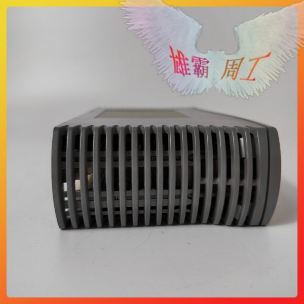
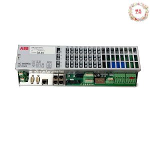
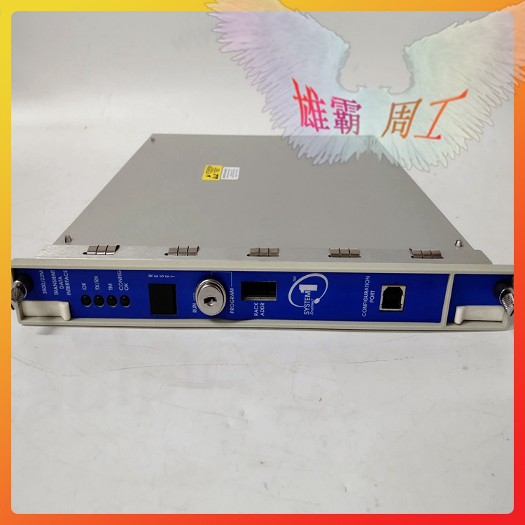
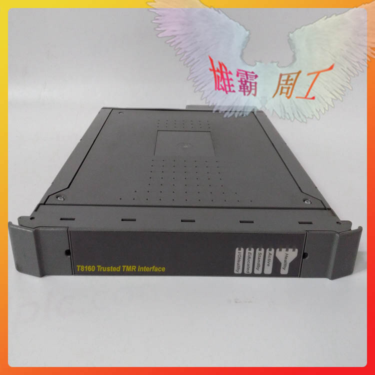
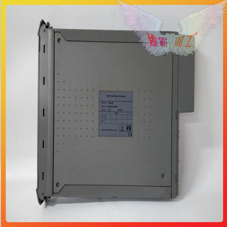
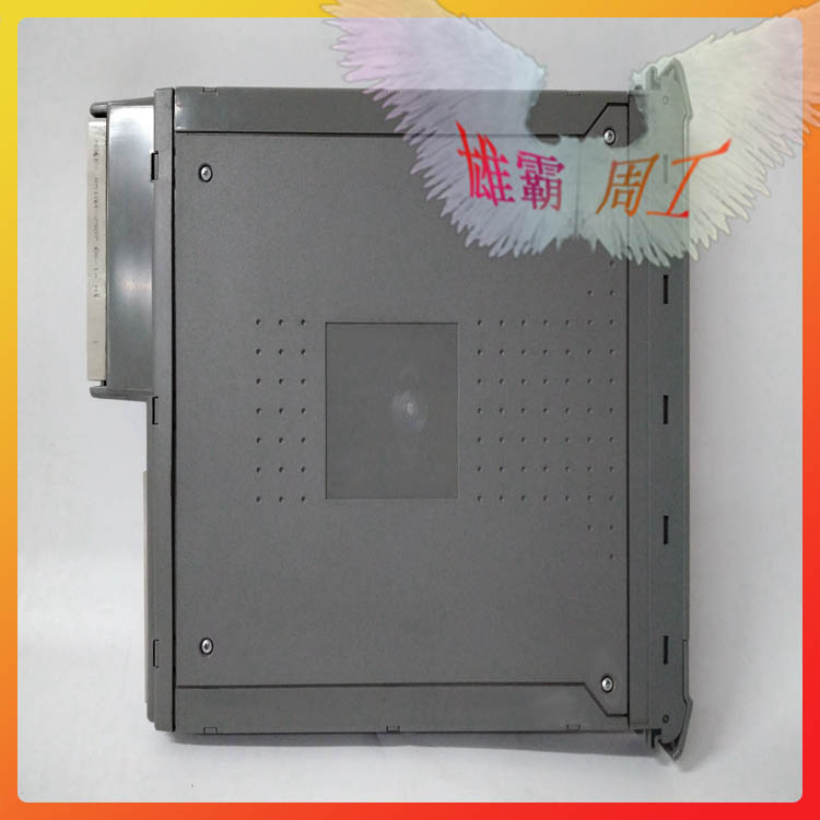
ICS TRIPLEX 151661 4013-2255 LCI adapter controller
ICS TRIPLEX 151661 4013-2255 LCI adapter controller
| Brand Name | ICS Triplex |
| Model | 151661 4013-2255 |
| Product type | N/M |
| Condition | New |
| Gross Weight | 1kg |
| Packing Size | 12.6″ x 7.9″ x 8.8″ (30 cm x 20 cm x 20 cm) |
| Country of Origin | USA |
| Lead Time | In Stock |
| Shipping Port | Xiamen |
| Payment | T/T |
| Sales Price | Inquiry |
| Color | Depends on material |
| Warranty | 12 months |
| Lead time | 3-7 work days |
| Courier partners | FedEx,DHL, UPS, TNTand EMS |
151661 4013-2255 Serial Ports
There are two connectors available to access the RS232 ports. Bank 1 provides a full RS232
interface. Bank 2 provides a partial RS232 interface with connections limited to TX, RX, RTS
and CTS.
151661 4013-2255 Serial Ports
1. There are eight connectors available to directly access the four RS485 ports. Banks 1
and 2 cannot be used in the RS485 mode if the Trusted Communication Interface is
configured for RS232 on these ports.
2. The RS485 ports are provided with two connectors per port. Each port is provided
with link selectable 120 Ω alternating current (ac) termination on both the transmit
and receive circuits as shown in the table below.
3. The ac coupled termination is used so as to reduce the current drawn on the
transmission line during the idle state. The use of two connectors and link selectable
termination is to make the configuration of multiplexed transmission lines simpler.
This method also provides the termination close to the transceivers thus avoiding
unnecessary reflections on the line.
2.3. Examples
RS485 FULL DUPLEX LINK
This is a point to point 4 wire link. The connections to the Termination Assembly should be
to Connector 1 with the TX/RX Termination link fitted.
RS485 FULL DUPLEX MULTIPLEXED
This is the most complicated system.
If the Termination Assembly is at the start of the multiplexed chain then Connector 1 is used
and the TX/RX Termination link is fitted.
If the Termination Assembly is in the chain then the Connector 1 is used to connect the
chain in and connector 2 is used to wire out to the next device. No links are fitted for this
port.
If the Termination Assembly is the last device in the chain Connector 1 is used and both the
TX Termination Link and the TX/RX Termination Link are fitted. The TX Termination link is
used here so that both ends of the line with multiple transmitters connected are
terminated.
RS485 Half Duplex Multiplexed
This is the 2 wires 485 system that is only wired on the RX/TX wires.
If the Termination Assembly is at the start or end of the transmission line Connector 1 is
used and the TX/RX Termination link is fitted.
If the Termination Assembly is in the transmission line then Connector 1 is used to connect
the chain in and Connector 2 is used to wire out to the next device. No links are fitted for
this port.
2.4. RS485 Hints
The signal ground on the RS485 links must always be connected otherwise the
communications between the devices may be unreliable. When specifying cable for these
connections allowance should be made for the signal ground connection. If screened cable
is used the signal ground should not be connected to the screen. It is usual to connect the
screen to the chassis earth at one end only.
Some manufacturers tend to use + and – designations on their equipment for labelling the
pairs. Since there is no standard as to how these match up with the EIA circuit designators
the following may be useful:
With the transmission line in the ‘Idle’ or ‘Off’ state connect a multimeter on the
volts range across the pair. When the multimeter reads a negative voltage the +ve
terminal of the multimeter is connected to A and the –ve terminal is connected to B.
2.5. Ethernet ports
Ethernet ports 1 (TCP/IP 0) on J6 and 2 (TCP/IP 1) on J8 are provided with connections to
10/100BaseT networks via RJ45 connectors.
| ICS TRIPLEX | T8311 | ICS TRIPLEX | T8480C | |
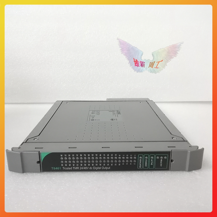
| ICS TRIPLEX | T9100 | ICS TRIPLEX | T8461 | |
| ICS TRIPLEX | TC-801-02-4M5 | ICS TRIPLEX | T8451 | |
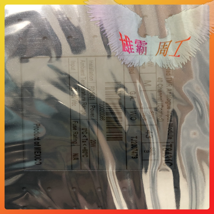
| ICS TRIPLEX | TC-305-01-5M0 | ICS TRIPLEX | T8431C | |
| ICS TRIPLEX | TC-303-01-2M0 | ICS TRIPLEX | T8431 | |
| ICS TRIPLEX | TC-301-02-2M0 | ICS TRIPLEX | T8403C | |
| ICS TRIPLEX | TC-215-01-6M5 | ICS TRIPLEX | T8110B | |
| ICS TRIPLEX | TC-215-01-4M5 | ICS TRIPLEX | T8100 | |
| ICS TRIPLEX | TC-201-01-6M5 | ICS TRIPLEX | 9852*4 cable | |
| ICS TRIPLEX | TC-201-01-4M5 | ICS TRIPLEX | 9852*4 | |
| ICS TRIPLEX | T9481 | ICS TRIPLEX | 9852*3 cable | |
| ICS TRIPLEX | T9451 | ICS TRIPLEX | 9852*3 | |
| ICS TRIPLEX | T9432 | ICS TRIPLEX | 9852*2/9832*1 | |
| ICS TRIPLEX | T9402 | ICS TRIPLEX | 9852*1/9802*2 cable | |
| ICS TRIPLEX | T9310-02 PN-175486 | ICS TRIPLEX | 9852*1/9802*2 | |
| ICS TRIPLEX | T9310-02 | ICS TRIPLEX | 9852*1 | |
| ICS TRIPLEX | T8300 | ICS TRIPLEX | 9852*1/9802*2 | |
| ICS TRIPLEX | T8231 | ICS TRIPLEX | 9832*3 cable | |
| ICS TRIPLEX | T8193 | ICS TRIPLEX | 9832*2 cable | |
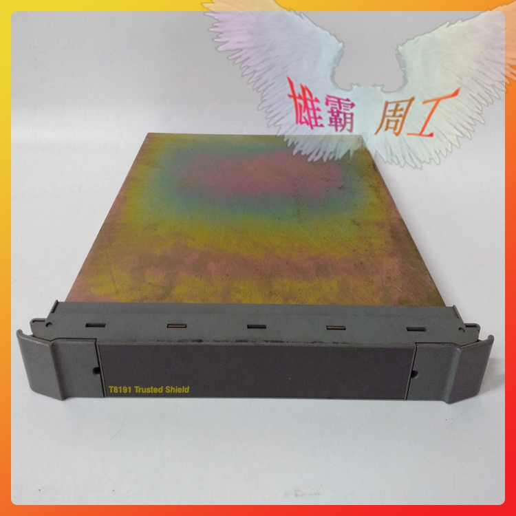
| ICS TRIPLEX | T8191 | ICS TRIPLEX | 9802*3 cable | |
| ICS TRIPLEX | T8160 | ICS TRIPLEX | 9802*1/9852*2 cable | |
| ICS TRIPLEX | T8151B | ICS TRIPLEX | 9802*3/9832*1 cable | |
| ICS TRIPLEX | T8110C | ICS TRIPLEX | 151661 4013-2255 | |
| ICS TRIPLEX | T8403 | ICS TRIPLEX | 1433/09232486825 | |
| ICS TRIPLEX | T8314 | ICS TRIPLEX | T8312-4 |