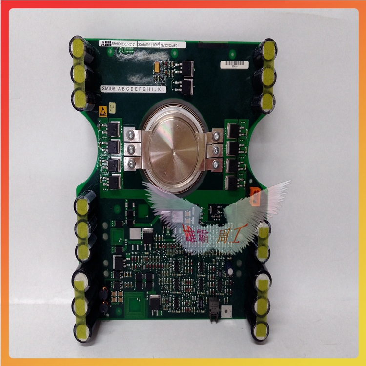


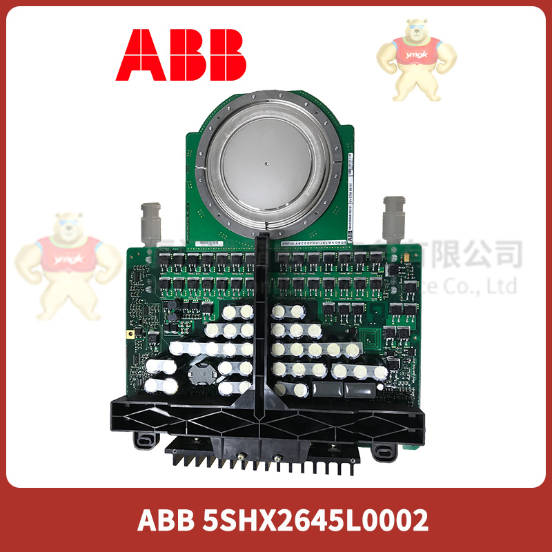
5SHX2645L0002 3HB012961R0001 ABB Semi controlled device
5SHX2645L0002 3HB012961R0001 ABB Semi controlled device
Article number :5SHX2645L0002 3HB012961R0001
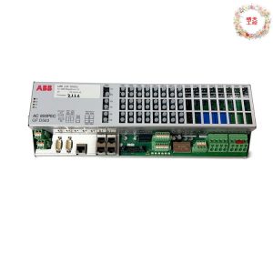
Communication protocol ABB’s DriveBus
Master or slave Master
Transmission speed 8 Mbit/s
Line redundancy No
Module redundancy No
Hot Swap Yes
Used together with HI Controller No
Contact : Zoe
WhatsApp: +86-15359298206
Phone: +86-15359298206 (Wechat)
E-mail: 2851759107@qq.com
QQ : 2851759107

working principle
working principle
Structural elements
Characteristics of thyristor
“At the touch”. However, if the negative voltage is applied to the anode or control electrode, the thyristor cannot be turned on. The function of the control pole is to make the thyristor turn on by applying a positive trigger pulse, but not turn it off. So, what method can be used to turn off the conducting thyristor? By turning off the thyristor on, you can disconnect the anode power supply (switch S in Figure 3) or make the anode current less than the minimum value of maintaining continuity (called the maintaining current). If AC voltage or pulsating DC voltage is applied between the anode and cathode of the thyristor, the thyristor will turn off automatically when the voltage exceeds zero.
Application type
Figure 4 shows the characteristic curve of bidirectional thyristor.
It can be seen from the figure that the characteristic curve of bidirectional thyristor is composed of curves in the first and third quadrants. The curve in the first quadrant shows that when the voltage applied to the main electrode makes the polarity of Tc to T1 positive, we call it the forward voltage, which is represented by the symbol U21. When the voltage gradually increases to the turning point voltage UBO, the thyristor on the left side of Figure 3 (b) will trigger the conduction. At this time, the on-state current is I21, and the direction is from T2 to Tl. It can be seen from the figure that the larger the trigger current is, the lower the turning voltage is. This situation is consistent with the trigger conduction law of ordinary silicon controlled rectifier. When the voltage applied to the main electrode makes the polarity of Tl to T2 positive, it is called the reverse voltage, which is represented by the symbol U12. When this voltage reaches the turning voltage value, the thyristor on the right of Figure 3 (b) will trigger conduction, and the current at this time is I12, and its direction is from T1 to T2. At this time, the characteristic curve of bidirectional thyristor is shown in the third quadrant of Figure 4.
Four triggering methods
Because on the main electrode of the bidirectional thyristor, it can be triggered and conducted regardless of the positive or negative voltage applied, and whether the trigger signal is positive or negative, it has the following four triggering methods: (1) When the voltage applied by the main electrode T2 to Tl is positive voltage, the voltage applied by the control electrode G to the first electrode Tl is also positive trigger signal (Figure 5a). After the bidirectional thyristor triggers the conduction, the direction of current I2l flows from T2 to T1. It can be seen from the characteristic curve that the bidirectional thyristor trigger conduction law is carried out according to the characteristics of the second quadrant. Because the trigger signal is positive, this trigger is called “positive trigger of the first quadrant” or I+trigger mode. (2) If the forward voltage is still applied to the main electrode T2, and the trigger signal is changed to the reverse signal (Fig. 5b), then after the two-way thyristor is triggered, the direction of the on-state current is still from T2 to T1. We call this trigger “negative trigger in the first quadrant” or I – trigger mode. (3) Apply the reverse voltage U12 to the two main electrodes (Fig. 5c), input the forward trigger signal, and after the two-way thyristor is turned on, the on-state current flows from T1 to T2. The bidirectional thyristor works according to the third quadrant characteristic curve, so this trigger is called III+trigger mode. (4) The reverse voltage U12 is still applied to the two main electrodes, and the input is the reverse trigger signal (Fig. 5d). After the two-way thyristor is turned on, the on-state current still flows from T1 to T2. This trigger is called Ⅲ – trigger mode. Although the bidirectional thyristor has the above four trigger modes, the trigger voltage and current required for the negative signal trigger are relatively small. The work is relatively reliable, so the negative trigger mode is widely used in practical use.
| Other relevant models |
| 5SHX0360D0001 IGCT MODULE 38 MM/6KV, HL000384P0101, 3BHB004027R0101 |
| 5SHX0660F0001 3BHB003387R0101 GVC703AE01 3BHL00386P0101 |
| 5SHX0660F0002 3BHE022333R0101 |
| 5SHX06F6004 3BHB003387R0101/5SXE05-0151/3BHB003151P104 |
| 5SHX0845F0001 3BHL000385P0101 3BHB003387R0101 5SXE05-0151 |
| 5SHX1060H0001 3BHB003230R0101 3BHL000392P0101 |
| 5SHX1060H0003 3BHE024415R0101 3BHB020538R0001 GVC714A101 |
| 5SHX10H6004 |
| 5SHX1445H0001 3BHL000391P0101 |
| 5SHX14H4502 3BHB003230R0101 5SXE05-0152 3BHB003023P201 |
| 5SHX1960L0004 3BHL000390P0104 |
| 5SHX2645L0002 3HB012961R0001 |
| 5SHX2645L0004 3BHL000389P0104 |
| 5SHX2645L0006 3BHB012961R0002 |
| 5SHY3545L0002 3BHE009681R0101 CVC750BE101 |
| KUC711AE 3BHB004661R0001 |
| KUC711AE01 3BHB004661R0001 |
| KUC711AE101 3BHB004661R0101 |
| KUC720AE 3BHB000652R0001 |
| 5SHY3545L0014 |
| 5SHY3545L0016 3BHB020720R0002 |
| 5SHY35L4520 |
| 5SHY4045L0004 3BHB021400R0002 |
| 5SHY4045L0006 3BHB030310R0001 3BHE039203R0101 GVC736CE101 |
| 5SHY5045L0020 AC10272001R0101 5SXE10-0181 |
| 5SHY5055L0002 3BHE019719R0101 GVC736BE101 |
| 5SHX1060H0003 |