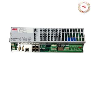
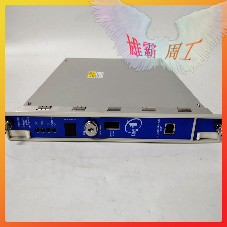
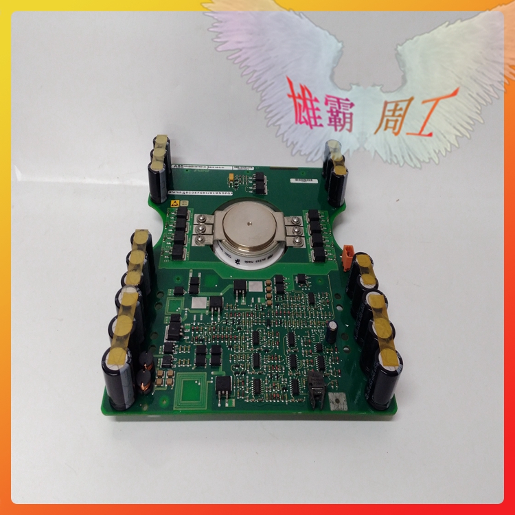
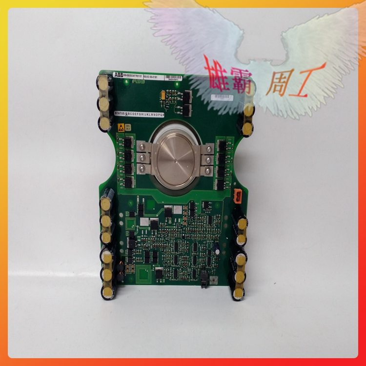
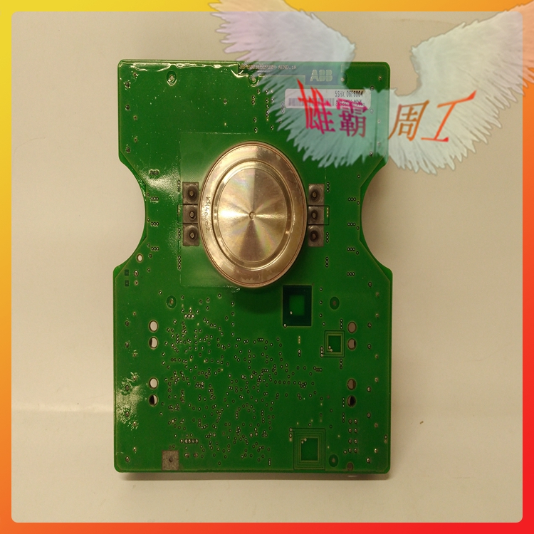
5SHX06F6004 3BHB003387R0101 ABB 5SHY series
5SHX06F6004 3BHB003387R0101 ABB 5SHY series
Article number 5SHX06F6004 3BHB003387R0101
Communication protocol ABB’s DriveBus
Master or slave Master
Transmission speed 8 Mbit/s
Line redundancy No
Module redundancy No
Hot Swap Yes
Used together with HI Controller No
Contact : Zoe
WhatsApp: +86-15359298206
Phone: +86-15359298206 (Wechat)
E-mail: 2851759107@qq.com
QQ : 2851759107
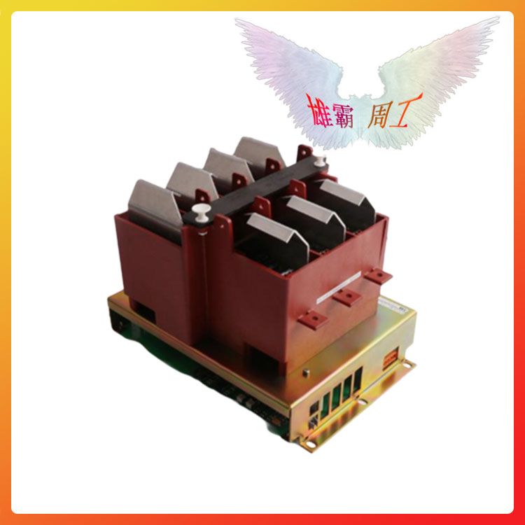
Silicon Controlled Rectifier (SCR) is a high-power electrical component, also known as thyristor. It has the advantages of small size, high efficiency and long service life. In the automatic control system, it can be used as a high-power driver to control high-power equipment with low-power controls. It has been widely used in AC and DC motor speed regulation system, power regulation system and servo system.
Thyristors are divided into unidirectional thyristor and bidirectional thyristor. Bidirectional thyristor is also called three-terminal bidirectional thyristor, or TRIAC for short. Bidirectional thyristor is structurally equivalent to the reverse connection of two unidirectional thyristor, which has the function of bidirectional conduction. Its on-off state is determined by the control pole G. Adding positive pulse (or negative pulse) to control pole G can make it conduct forward (or reverse). The advantage of this device is that the control circuit is simple and there is no reverse voltage withstand problem, so it is particularly suitable for use as an AC contactless switch.
structure
We use unidirectional thyristor, which is commonly known as ordinary thyristor. It is composed of four layers of semiconductor materials, with three PN junctions and three external electrodes (Figure 2 (a)): the electrode from the first layer of P-type semiconductor is called anode A, the electrode from the third layer of P-type semiconductor is called control electrode G, and the electrode from the fourth layer of N-type semiconductor is called cathode K. From the circuit symbol of the thyristor (Fig. 2 (b)), it can be seen that it is a unidirectional conductive device like the diode. The key is to add a control pole G, which makes it have completely different working characteristics from the diode.
The P1N1P2N2 four-layer three-terminal device with silicon single crystal as the basic material was started in 1957. Because its characteristics are similar to vacuum thyristors, it is generally known internationally as silicon thyristors, or thyristor T for short. Because the thyristor was originally used for static rectification, it is also called silicon controlled rectifier element, or SCR for short.
In terms of performance, silicon controlled rectifier not only has single-guide electricity, but also has more valuable controllability than silicon rectifier element (commonly known as “dead silicon”). It only has on and off states.

Thyristors can control high-power electromechanical equipment with milliampere current. If the power exceeds this power, the average current phase allowed to pass will be reduced due to the significant increase in switching loss of components. At this time, the nominal current should be degraded for use.
Thyristors have many advantages, such as controlling large power with small power, and the power amplification factor is up to hundreds of thousands of times; Very fast response, turn on and off in microseconds; No contact operation, no spark, no noise; High efficiency, low cost, etc.
Weakness of thyristor: poor static and dynamic overload capacity; Easy to be disturbed and misled.
Thyristors can be classified into bolt type, flat plate type and flat bottom type.
Structure of thyristor element
Regardless of the shape of silicon controlled rectifier, their tube core is a four-layer P1N1P2N2 structure composed of P-type silicon and N-type silicon. See Figure 1. It has three PN junctions (J1, J2, J3). The anode A is drawn from the P1 layer of the J1 structure, the cathode K is drawn from the N2 layer, and the control electrode G is drawn from the P2 layer. Therefore, it is a four-layer three-terminal semiconductor device.