")
")

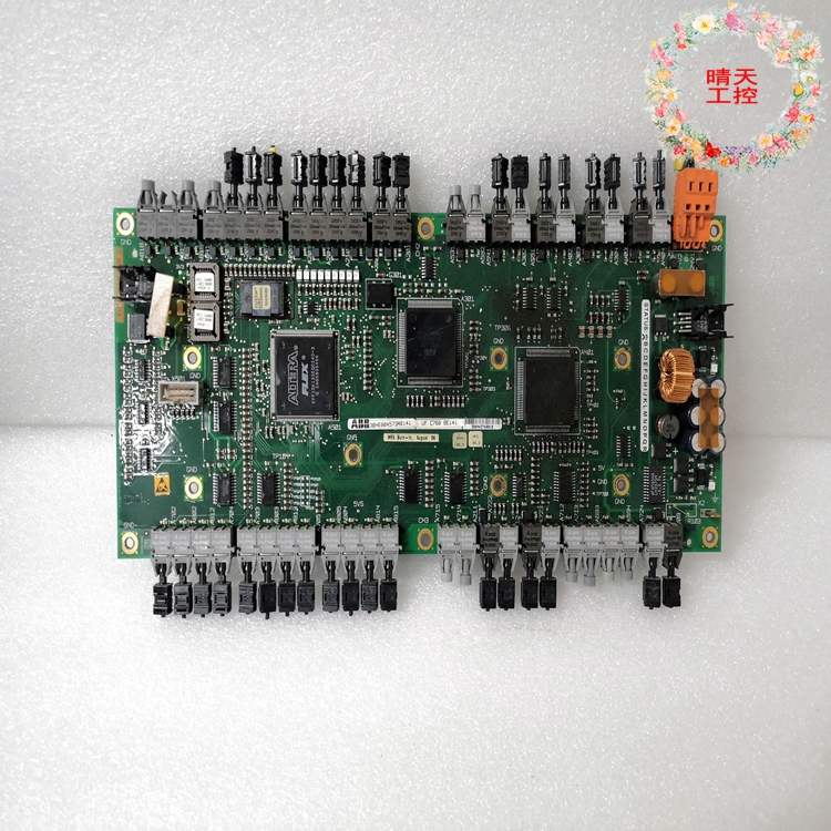
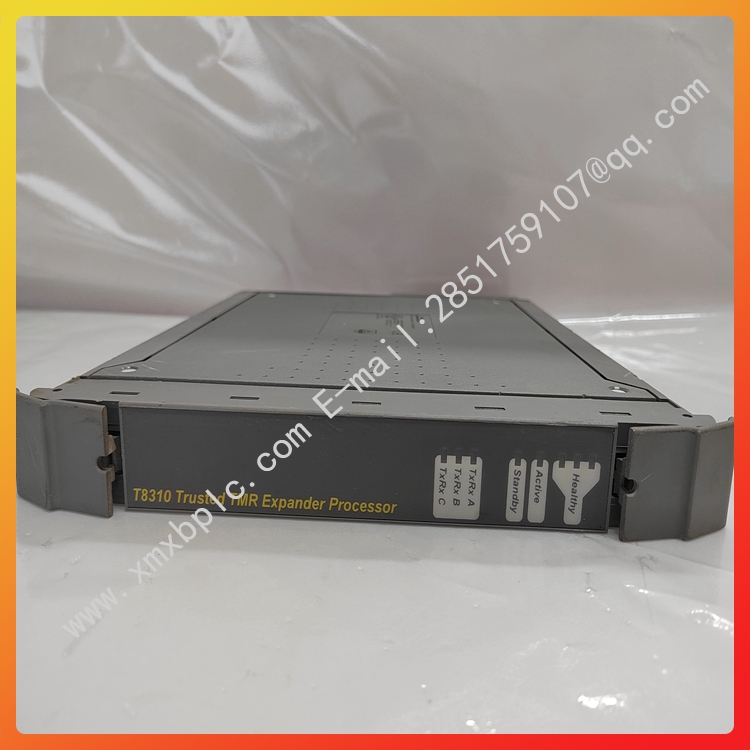
GE 12HFA51A42HPLC automated spare parts industrial control system card
Brand ABB color Standard Application Industrial height 325mm rated current 660mA
Protection Level IP45 Suitable for motor power 36KW Application Site Power Industry Material Code GJR2391500R1220 Power industry HIEE401782R0001 Part No. 12HFA51A42H
Applicable pipe 2 Whether imported is weighing 6.88 kg can be sold nationwide

GE 12HFA51A42HPLC automated spare parts industrial control system card
MB86S02 video image sensor collects video image information under the control of FPGA. MB86S02 starts video signal acquisition after receiving the acquisition command from PC. FPGA, as the core control unit of the system, is not only responsible for video image acquisition. It is also responsible for the pre-processing of video image information and the data interaction between each unit module of the system. In view of the large amount of video image data, in order to ensure the real-time requirements of the system, the system adopts large-capacity off-chip SDRAMR to cache the collected video image information. The SDRAM controller is implemented by FPGA, and the video image information must be filtered by FPGA after being cached by SDRAM. In order to eliminate the noise interference in the image information, the system uses the median filter to process the collected video information, and the filtered data enters the DSP through the FPGA internal FIFO for the next step of compression processing. After powering on the DSP, the bootstrap program is self-loaded first and waits for the request from FPGA. After receiving the request from FPGA, the DSP establishes an EDMA channel to obtain video data from FPGA. After storing a full frame, the video image is compressed by JPEG and the compressed video image information is cached by FIFO. Under the control of FPGA, the data cache of the USB interface controller is written, waiting for the reading request of the PC, and the USB interface controller writes the data to port 1 of PDIUSBD12 after receiving the reading request of the PC, so that the PC can read the data in the next step.
2 Overall design of system software
The software design of the system can also be divided into two parts according to the overall division of the hardware structure. The operation of the whole system is shown in Figure 2. The programs of FPGA and DSP run independently and complete real-time data interaction through interrupt signals. The instruction from FPGA to DSP is to send an EDMA request through FPGA, and the DSP establishes an EDMA channel in response to the EDMA request and starts to read the pre-processed data from the FIFO. When the DSP transmits data to the FPGA, it sends an interrupt signal to the FPGA. Let it read the compressed image data out of the FIFO.
The whole system workflow can be simply described as follows: After the system is powered on, the DSP is bootstrapped by flash first, and the boot program is run, and then it is transferred to the EDMA waiting state. After initialization, the FPGA waits for the external image acquisition command. After receiving the image acquisition command, the image acquisition begins, and the acquired image is preprocessed. After storing a certain amount of data, FPGA sends EDMA request to DSP through half-full signal, waiting for DSP response. Once DSP receives EDMA request from FPGA, it immediately establishes EDMA channel, reads data from FIFO to L2 memory, and starts image compression after storing one frame of image. After an image compression is completed, the DSP sends an interrupt signal to the FPGA, and the FPGA begins to read the compressed image data from the FIFO after receiving the interrupt signal. After reading a frame of data, the encoded signal is judged whether it is valid. If it is valid, the next frame image is compressed according to the same rules. If it is invalid, the DSP is notified to end.
GE 12HFA51A42HPLC automated spare parts industrial control system card
GE 12HFA51A42H
GE 12HGA11J52
GE 269 PLUS-D/O-100P-125V
GE 369-HI-0-0-0-0
GE 489-P5-LO-A20
GE 5136-PFB-VME
GE 94-164136-001
GE CT7P70500470CW24
GE DS200TCQAG1BHF
GE DS3800HPIB
GE H200I
GE HE693STP104AX
GE HE693STP110
GE IC200ALG620
GE IC200GBI001
GE IC660BBD025
GE IC660EBD020
GE IC660ELB912G
GE IC660ELD100A
GE IC660TSA100
GE IC670CBL001
GE IC670CHS001
GE IC670CHS002
GE IC670CHS101